Amiga's circuits
Your base Amiga is designed for simple assembly and maintenance. It contains three main circuits essential for operation:
Power Circuit
This circuit provides power to all other circuits and the motors, operating at 44 VDC (nominal). Power is drawn from the batteries via IEC C14 connectors and distributed using the cross bar and truck bar harnesses via Anderson connectors.
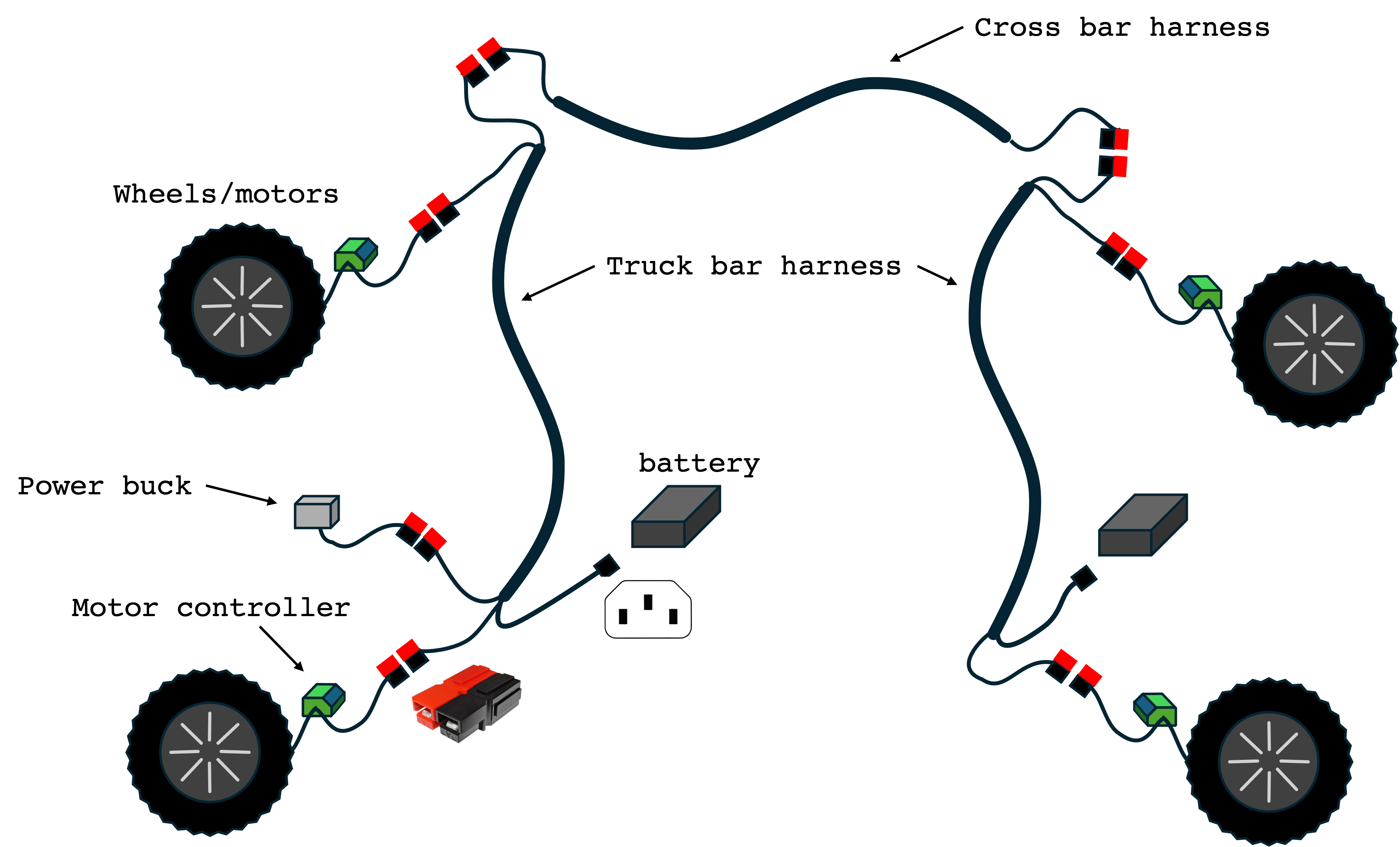
We use the motor names to identify the harnesses, the A-D harness is secured to the truck bars as it is also the case for the B-C harness on the other side. The cross harness that links the two sides is secured using fir tree fasteners and zip ties.
Each fork also includes an additional Anderson connector for connecting other 44V accessories.
Motors
Each wheel in your Amiga contain an electric motor and gear reduction controlled by a controller placed inside the side panel. Each motor have the following specs:
| Parameters | Values |
|---|---|
| Rated power | 250 W |
| Operational Voltage | 36 ~ 43 VDC |
| Reduction ratio | 1:30 |
Each motor requires its own motor controller and, despite sharing the same hardware, they have the tires mounted differently. Make sure your motor is adequate to each side of your Amiga when assembling it.
When not powered (including when your physical STOP button is pushed), the motors run freely. Make sure your are in level ground or have a physical barrier (like a wheel chock) when operating in slopes.
CAN Bus
Your Amiga uses a CAN network to send control messages between the dashboard, pendant, motors, and tools (if available). This network operates at 24 VDC provided by the Power Buck installed in one of the forks (typically fork B). To prevent current surges on the CAN Bus (and on the ESTOP circuit), there is a fuse box right out of the Power Buck. It uses 10 Amps automotive fuses.
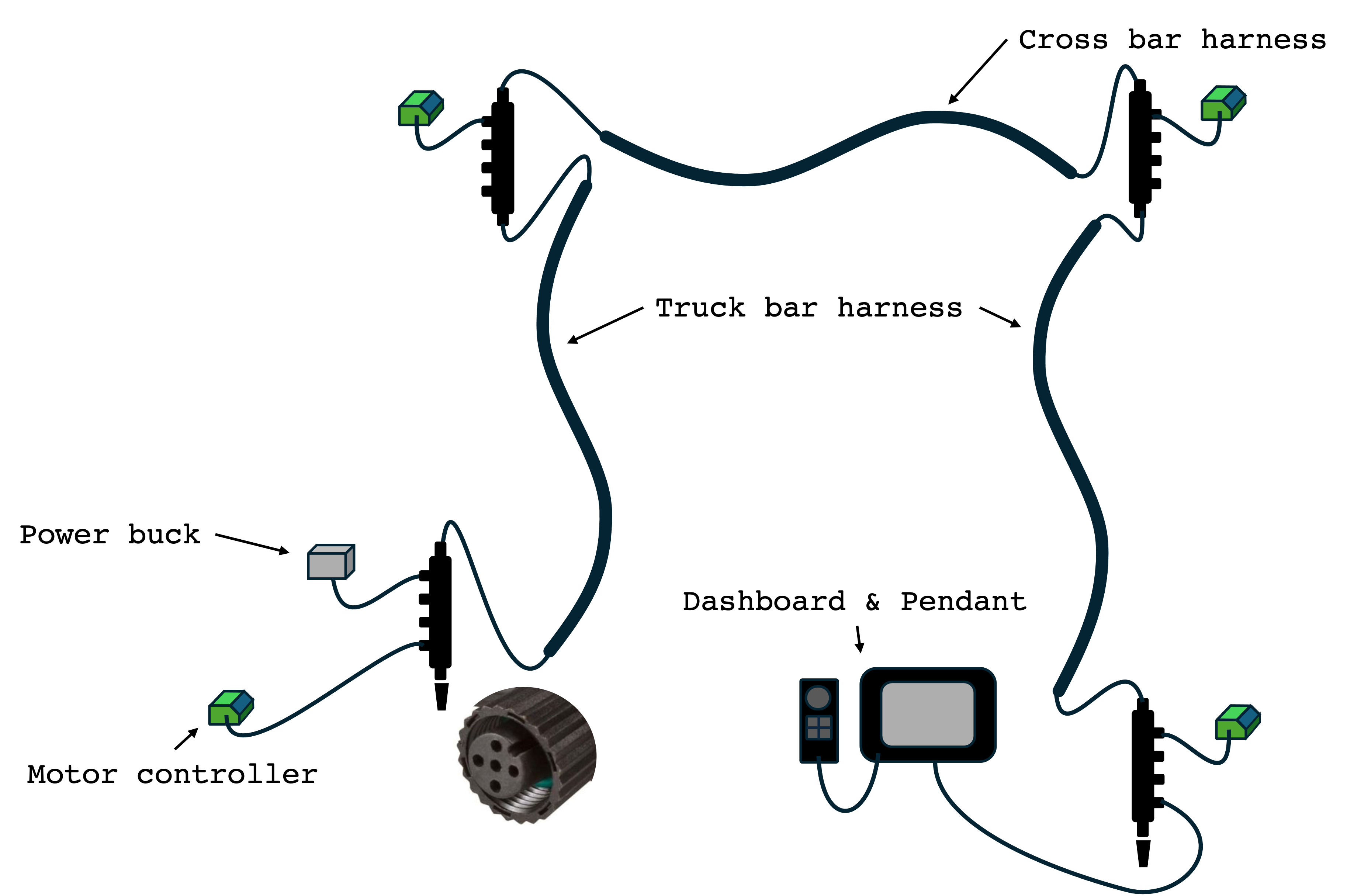
Inside each fork panel, NMEA-2000 CAN hubs connect provide a connection point to tie the motor controllers to the CAN network. Extra ports are available to connect additional CAN devices. Termination resistors are placed at either end of the CAN network to ensure that the CAN signals are not reflected from the cable ends. For best results, the CAN bus termination should match the nominal impedance of the cables, which for ISO 11898-2 (high speed CAN) is specified at 120 Ohm.
When you can't detect power on your CAN bus (e.g. Dashboard and Brain won't boot), there is a high chance you have a blown fuse. Inspect your fuse integrity visually and/or using a multimeter before proceeding with troubleshooting.
ESTOP Circuit
The primary role of the E-stop circuit is to cut power from the motor controllers at start up (preventing any possibility that the Amiga would simply take off) as well as in emergency situations when the Amiga must be stopped. This circuit also receives 24 VDC from the power buck and distributes via M8 connectors to the motor controllers, tools, and the physical STOP button.
Engaging the E-stop button cuts power to the motor controllers but it does not provide a braking system. Be prepared for the Amiga to roll freely if the button is engaged while the robot sits at an `incline.
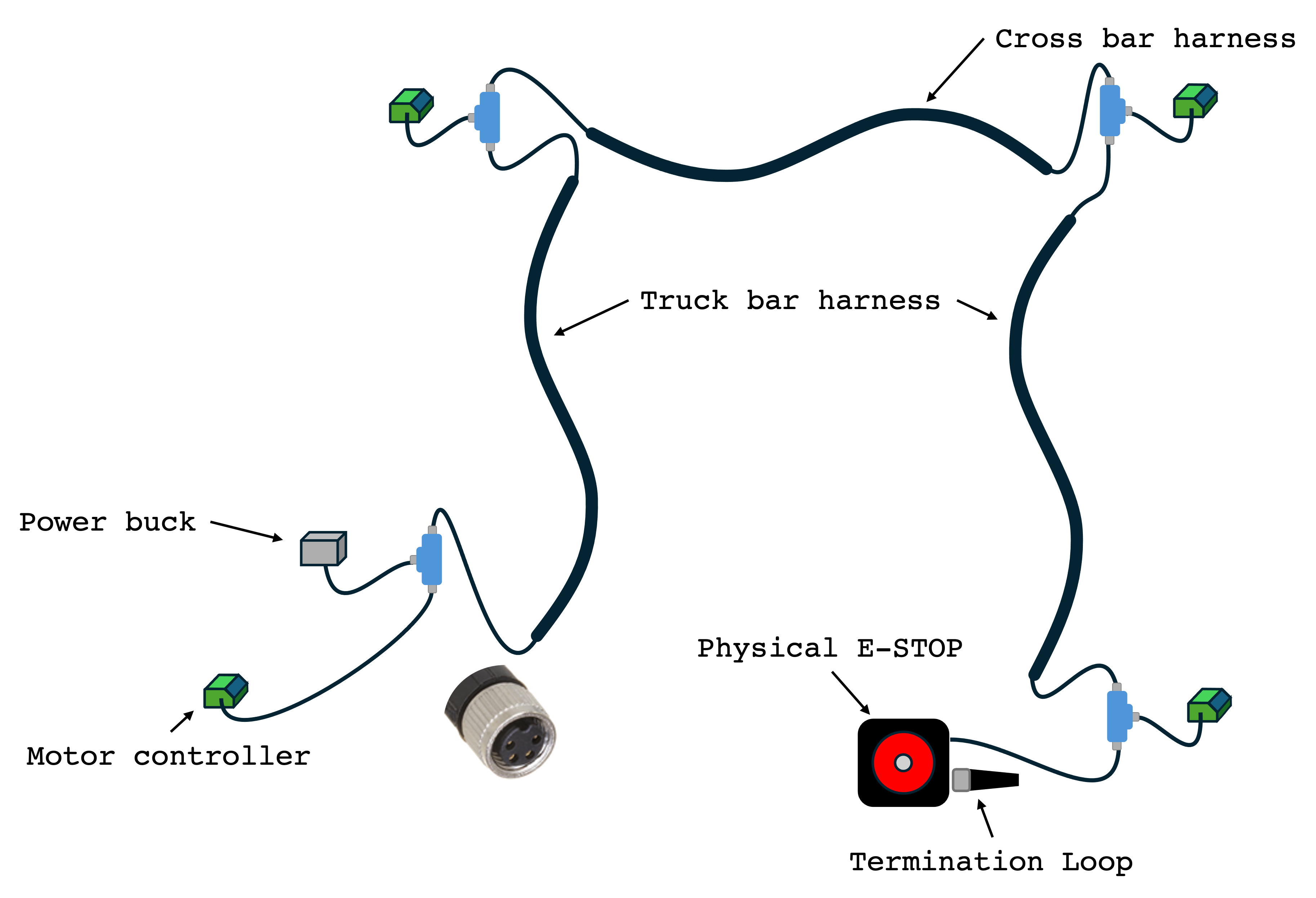
Inside each fork panel, blue M8 Tees allow motor controllers to receive the E-STOP signal. The tees are simply junctions that allow for the creation of a closed loop system across all the peripherals attached to the E-Stop circuit. Additional components such as the H-bride and PTO must be tied to the E-stop circuit for safety purposes. This is done by adding t junctions and cables to bring in these peripherals into the loop.
The STOP button physically opens the circuit. It includes a second connector for adding more buttons; if not in use, this connector should have a termination loop. Without the termination loop the circuit remains open, leaving the robot in E-STOP status.
Motor Controller
Each motor use a controller that requires all three circuits to operate. The connections for each circuit are inside the side panels on a custom harness. Removing any of the connections will result on a CAN and/or E-STOP circuit errors. Refer to Debugging Error Codes section to learn more about errors and solutions.
When any of the motors have an error, your Amiga will be inoperative until all errors are cleared.
If you are in and unsafe space for debugging, you can disable the faulty motor/controller going to
Dashboard Settings > Settings > mXX_on
and setting to False. Note that:
m10= motor Am11= motor Bm12= motor Cm13= motor D
Revert the motor back to True to resume debugging.