Dashboard User Guide
This guide is subject to change with each new update to the Dashboard.
The latest version is Dashboard Firmware release v0.7.0.
Dashboard overview video
Start Page
This is the start page on the dashboard. It will appear when you first turn on your Amiga. Here is where you can change the display's language. You may choose between English, Spanish, and French. Pressing the START button will take you to the home screen.
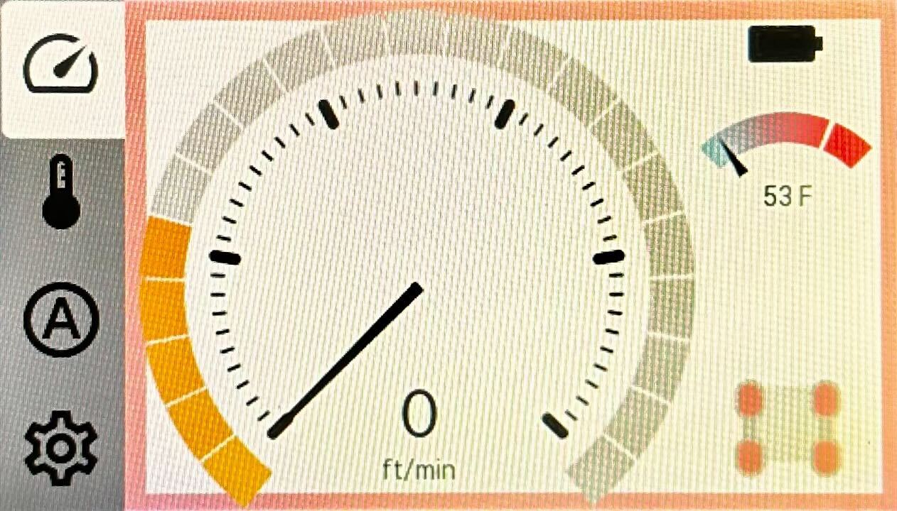
Home Screen
This is the home screen of the dashboard. In the center sits the speedometer, where you can switch between metric and standard units and adjust to the travel speed of your Amiga.
On the right side of the screen you will see several icons displaying:
- Battery Level
- Average motor temperature
- Connection to Pendant
- Preview of each motor's health
You can always come back to this screen by pressing the upper left icon on the dashboard.
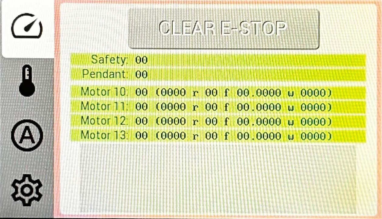
Motor Status Screen
In this screen you can see the control state of your Amiga:
- Active
- Cruise
- Auto Ready/Active
- E-Stopped
You will also see details on each motor / motor controller's:
- Voltage
- RPM
- Temperature
- Current draw
Lastly, CAN bus states will appear on the right side of the display.
Auto Control Screen
If you have an Intelligence Kit mounted on your Amiga and have some tracks recorded in Autoplot, activating the auto mode on this screen is what brings autonomous control into action.
From this screen, you will be able to:
- Enable and disable Auto Control
- Monitor the Auto Control state
- Monitor the commanded & measured speed of your Amiga
You can also use micro-controllers to command your Amiga. For an example of how to do so, please follow the instructions in this FPV example
Starting on Dashboard Firmware v0.5.0 and AmigaOS v2.3.0 the Brain has tool control
capabilities.
Therefore, when Auto Control is ENABLED, a blue outline will appear around the Dashboard and the
pendant commands will be bypassed. Tool control is thus carried out in the Autoplot app, a browser
window, or your custom application.
If manual control is needed, disable Auto Control on E-STOP your Amiga using the physical button.
General Settings
In this screen, you can make configuration changes to your Amiga's:
- Settings
- Pendant
- H Bridge
- ID
- PTO
- Advanced
Configuration Settings
General configuration settings are located in this tab. The configuration changes you can make on this page are:
Unless stated otherwise, linear engineering units will be determined by your settings, or by
pressing the digital speed on your main screen.
Similarly, angular units refer to counterclockwise rotation around the Z axis of the
Robot Frame (origin at the ground level
at the center of the robot).
wheel_track: width of your Amiga, from center of A motor to center of B motor.wheel_front_track: width of front wheels, from center of C motor to center of D motor. Use0if equal towheel_trackwheel_back_reverse: reverse B and C motors rotation. Used only in the very specific case you have all 4 wheels in line.v_max_default: default max speed setting when your dashboard reboots.max_turn_rate: maximum angular speed (in RPM) when rotating the robot on its center (zero turn).min_turn_rate: minimum angular speed (in RPM) when rotating the robot on its center (zero turn).turtle_v: maximum linear speed the robot will drive when battery is lower thanbatt_hithreshold.turtle_turn_rate: maximum angular speed (in RPM) the robot will turn on its axis when battery is lower thanbatt_hithreshold.max_accel: maximum angular acceleration (inrad/s**2)flip_joystick: reverse joystick controls (useful when user operates facing robots back, for example)pendant_deadband: sensitivity of the pendant's joystick. Reduce it if you want your pendant to respond to smaller movements. Too small values may cause unstable behavior.steering_gamma: responsiveness of the pendant's joystick to steering. Larger values lead to steeper curves.batt_lo: threshold in VDC where the robot will switch to turtle mode and be limited toturtle_vspeed. Used to allow user to drive to a safe location before complete shutdown. Default value is 40 VDC.batt_hi: threshold where the display will show full battery. Default value is 50 VDC.pto0_gear_ratio: gear ratio of your first PTO attachment.pto1_gear_ratio: gear ratio of your second PTO attachment.default_pto_rpm: default PTO rotation for both PTOs.min_pto_rpm: minimum limit for both PTO attachments.max_pto_rpm: maximum limit for both PTO attachments.m10_on: boolean to turn motor A onm11_on: boolean to turn motor B onm12_on: boolean to turn motor C onm13_on: boolean to turn motor D onauto_hold_mode: when ON, increase motor torque on stops, increasing precision when stopped on slopes. This setting increase power consumption considerably and should be used only in very specific cases. Contact support@farm-ng.com to explore other options.lang: 0 for English, 1 for Spanish, 2 for French. Can be changed in Setup page directly.units_dst: speed units on your main gauge. Press your digital speedometer for verbose options.units_temp: temperature units on your dashboard. Press the thermometer on you main display for verbose options.
You should press the E-stop button prior to turning the motors on / off
(with m10_on, m11_on, m12_on, m13_on).
Failure to do so will brake the wheels until it is pressed -> released.
When in question of your Dashboard settings, go to Advanced Settings > Factory Settings Reset, and get the default values set all at once.
The Pendant Settings
This is the hub for the pendant. Here is where you can confirm data reception and overall functionality. Pressing on the icon will take you to the calibration screen.
A green square around the center dot indicates that the your pendant is properly calibrated.
A purple square indicates the need to re-calibrate your pendant.
If your Amiga begins to move on its own at start up, chances are that your pendant needs to be calibrated. With the above image in mind (purple square around the white dot), your Amiga would move forwards and towards the right at start up.
Pressing the Pendant image on the right will show the latest button configurations.
The arrows (up/down/left/right) in the center of the pendant are used to select and engage with the H-Bridge(s).
H-bridge settings
An H bridge circuit allows you to apply a voltage across a load (i.e. a linear actuator)
in either direction. We currently support up to four h bridge modules on the Amiga.
They can be engaged momentarily or latched.
The up - down arrows are used to control the selected H bridge device(s)
and the left - right arrow keys are used to select between H-bridge devices.
Two H-bridge devices (0 & 1 or 2 & 3) can be coupled with the coupler button and actuated together.
Our 3 point hitch is temporarily engaged by the H bridge to lift and lower the A frame which you can use to engage a seeder. Alternatively, you can use the latching function in a sprayer system.
By default, the first H-bridge that is connected will fill the 0 position in green. You can switch between MOMENTARY and LATCHING states by tapping on the desired state on the Dashboard.
If you expect a H-bridge device but it is not showing up, please reach out to us via farm-ng's Support page.
ID settings
This page displays your Tractor Hardware ID, Dashboard Firmware version,
and enables you to launch the Updator App where you can carry out Over-the-Air updates.
Updator App
On the Updator App, you will be able to update your Amiga dashboard and Updator app itself
through here. You can use the Updator App to perform an Over-the-air update.
For more information about Firmware Updates or how to perform an update, please visit Dashboard Firmware Update
PTO settings
The PTO (power take-off) screen allows you to select between devices (PTO0 &PTO1), fine tune their settings and monitor their performance. We currently support up to two PTO's running at the same time.
When you connect a PTO device, you will have access to the following features:
- A slider control that enables you to increase or decrease the PTO's RPM.
- Directional control by means of a toggle switch on the touchscreen.
On the left side of the screen you will see a graph displaying the current PTO set-point & measured rpm values.
The default, min, & max values for the RPM slider can be configured on the settings page. The PTO gear ratio can also be configured on the settings page.
Occasionally a message stating that no PTO device has been detected will be accompanied by the following image. Inspect all cables and make sure they are properly connected.
If you expect a PTO device but it is not showing up, please reach out to us via farm-ng's Support page.
Advanced settings
This page allows you to deep dive into the dashboard's firmware
Reboot Dashboard: This will give a soft reboot to the dashboard without having to power cycle your Amiga.Factory Setting Reset: This setting will revert the general settings such aswheel_track,max_turn_rate, and more, back to the factory default values.- NOTE: These may not match the values when you first received your Amiga if you do not have the standard configuration.
Mount CIRCUITPY: When you would like to Mount CIRCUITPY to update the Dashboard Firmware, here is where you will do that in order for your computer to communicate with your Dashboard.Bootloader Mode: Similar toMount CIRCUITPY, when you would like to update the UF2 file on the dashboard you will need to place it in aBootloaderstate. With this button you can perform that action.
For more information about Firmware Updates or how to perform an update, please visit Dashboard Firmware Update
State Indicators
The state indicators are for defining and understanding which control state your Amiga is in.
These states include, but are not limited to, E-stopped, Auto_ready, and Cruise Control.
E-Stopped
When your Amiga is E-stopped, a red border will display around the edges of your dashboard screen. When your Amiga is in this state, your motor controller will be un able to move on command.
Cruise Control
This state will enable you to place your Amiga at a given speed and allow your Amiga to cruise
at that speed. When this control state is activated,
a green border will be at the edge of your dashboard screen.
Auto Control
This state will enable you to control your Amiga via external controls and through remote source.
Some of these sources include the virtual_joy_stick.
When you activate the auto_control feature on your dashboard.
You will see a yellow border appear around the edge of your dashboard.
This yellow border means your Amiga in the auto_ready state and once the connection is secure
it will then gain a green border meaning it is in the auto_active state.
For more information about Amiga Control States , please visit Amiga Control States